
Like any part of the manufacturing or fabrication process, welding is subject to human error from time to time. When weld defects occur as a result of incorrect welder technique or equipment settings, it can cause costly downtime and rework—and frustration.
When a weld defect appears, it’s important for welders to have the knowledge they need to fix the situation as quickly as possible. Faster troubleshooting leads to greater opportunities to add value to the welding operation through increased productivity and quality improvements.
The key to avoiding some of the most common weld defects is to know what they are and what steps you need to take to prevent them from happening.
Porosity
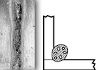 Porosity is among the most common weld defects. It can develop in many types of material—from aluminum to galvanized and carbon steel, among others—and is the result of gas getting trapped in the weld metal. Porosity can appear at any point on the weld, including along the length of the weld, on the inside (subsurface) or on the outside of the weld.
Inadequate shielding gas coverage is among the biggest culprits of porosity, and can be addressed in one of several steps. First, check the regulator or flow meter for adequate gas flow, increasing it as necessary. Check the gas hoses and welding gun for possible leaks and block off the welding area accordingly if drafts are present.
If you use a nozzle that is too small, spatter buildup in the nozzle or incorrect contact tip recess can also prevent proper shielding gas coverage. Be certain to use a large enough nozzle to shield the weld pool fully with shielding gas, keep the nozzle clean and follow the consumable manufacturer’s recommendation for contact tip recess.
Other causes and remedies for porosity include:
- Having dirty base material. Always be sure to follow proper cleaning procedures.
- Extending the wire too far from the nozzle. A good rule of thumb is to extend the wire no more than one-half inch past the nozzle.
- Wet or contaminated shielding gas cylinders. Replace damaged cylinders immediately.
- Damaged filler metals. Low hydrogen filler metals can pick up moisture. Always follow proper storage requirements.
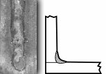
Lack of fusion and cold lap
 Cold lap and lack of fusion are terms for weld defects that are often used interchangeably. However, they are slightly different and can happen independently or in conjunction with one another.
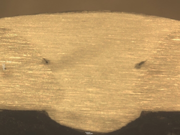
Lack of fusion is the result of the weld metal failing to fuse completely to the base metal or to the previous weld bead in multi-pass applications. Using an improper welding gun angle or incorrect travel speed tends to cause this defect. You can avoid this problem by maintaining a 0- to 15-degree gun angle during welding and by keeping the arc on the leading edge of the weld pool. It’s sometimes necessary to increase the travel speed of the welding gun to maintain the correct arc position.
Insufficient heat in the weld can also cause lack of fusion and can be easily remedied by increasing your voltage settings or wire feed speeds.
In addition to lack of fusion, incorrect travel speed can also result in cold lap. This causes the weld to overfill and essentially overlap on the toes of the weld. When the weld pool absorbs most of the energy of the arc—as opposed to the base material—cold lap is more likely to occur. Increasing travel speeds can help the weld fill in more smoothly and prevent this problem.
Burn-through
Burn-through is the result of the weld metal penetrating completely through the base material. Burn-through is especially common when welding thin materials—typically less than 1/8 inch or about 12 gauge. Excessive heat is the main cause of burn-through, but this defect can be easily rectified by lower the voltage or wire feed speed. Also consider increasing travel speeds—particularly when welding on thin aluminum—which is especially prone to heat buildup.
Excessive spatter
Excessive spatter can appear when using a variety of filler metals, such as self-shielded flux-cored wires or stick electrodes. This defect results when the weld puddle expels molten metal and scatters it along the weld bead. The result? Molten metal fuses to the base, causing bumps or spatter. Typically spatter needs to be removed mechanically, by scraping or grinding it off with a grinder.
Several scenarios within the welding process can contribute to excessive spatter, such as:
- Insufficient shielding gas
- Dirty base materials
- Too high voltage
- Too high travel speeds
- Too much wire stickout
You can avoid excessive spatter accumulation while you weld by: Ensuring proper shielding gas flow; Cleaning base materials thoroughly; Lowering the given weld parameter settings; And using a shorter stickout.
When a gas mixer does not feed a consistent gas blend or has been adjusted incorrectly, it can change the arc characteristics drastically, resulting in spatter. For example, if an application requires a conventional 75 percent argon/25 percent carbon dioxide shielding gas blend and this weld defect develops, it’s possible the mixer is delivering too much CO2, which tends to generate higher levels of spatter. Check the mixer and adjust it accordingly.
For self-shielded flux-cored wires, be certain to weld with straight polarity (electrode negative) and use a drag technique when welding to minimize the opportunity for spatter buildup.
While using flux-cored or metal-cored wires, low voltage could produce an excessive amount of spatter as well. If you see spatter accumulating, increase your voltage as needed.
The wrong size contact tip, a worn contact tip or the wrong contact-tip-to-nozzle recess can also cause excessive spatter and should be addressed accordingly, either by replacing the contact tip or switching to a tip that is the right size for the nozzle recess.
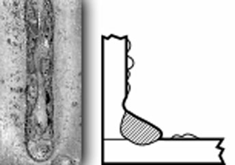
Concave and convex weld beads
Regardless of the welding process, the goal is to create a smooth, flat weld bead. Welds that are too concave or too convex can compromise the integrity of the finished product and are considered to be weld defects in some cases.
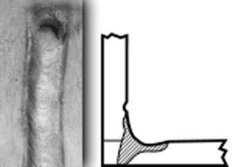
Concave weld beads are particularly prevalent when welding in vertical-down applications. And they’re simply the result of working against gravity. It’s difficult to keep the weld pool in the joint in this position, so the weld tends to be thinner at the throat. A good remedy is to adjust the parameters to a lower setting. This will create a weld pool that’s less fluid and more able to fill in the joint. If a concave weld bead appears in the flat or horizontal position, it’s typically the result of voltage that is too high, wire feed speed that is too slow or travel speed that is too fast. Adjust these factors accordingly to avoid a concave weld bead.
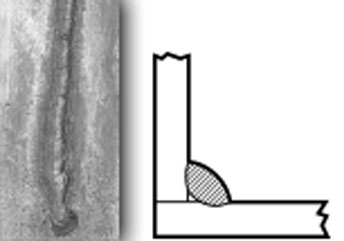
Convex weld beads present themselves as high, rope-like welds. They generally occur in flat and horizontal welding when the parameters for the material being welded are too cold. To prevent this, increase the voltage on your welding power source to avoid creating a convex weld bead.
Using the wrong shielding gas for a particular type of wire can also cause a convex weld bead. For example, if an application calls for a mixed argon shielding gas but the welder uses 100 percent argon, the weld pool will not be fluid enough. This prevents the weld from penetrating the joint. Instead, the bead will build up on top of the joint, causing a convex weld bead to form. Always follow the recommended welding procedures and use the materials with the proper shielding gas. Be sure to use the correct polarity for the wire, as well, to prevent this defect from happening.
Crater cracks
Crater cracks are small cracks that develop at the end of the weld. They can happen during any welding process and are sometimes called shrink cracks. This occurs when the weld crater has not been fully filled when completing a pass. The weld pool solidifies and the center of the crater pulls from the center of the weld bead. This is especially common when welding aluminum.
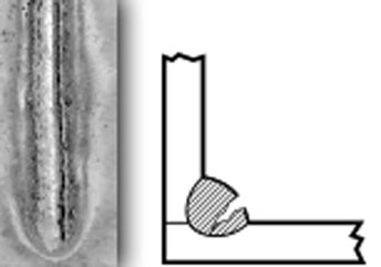
To prevent crater cracks, pause at the end of the weld to ensure enough filler metal has filled the weld pool or back step to fill it, moving back from the end of the weld, then forward. Some welders choose to solve crater cracks by pausing and welding a curlicue at the end of a pass. A double trigger technique also works to avoid a crater crack. To use this technique in a MIG welding application, release the trigger, pull it again to start the weld. Then release the trigger again to fill the crater.
Some wire feeders also have crater functions that can remedy this problem. To activate this function, the welder releases the trigger and the system automatically fills the crater.
In some applications—particularly those using submerged arc welding—run-off tabs are a common way to prevent crater cracks. Run-off tabs are metal tabs that the welder tacks to the end of the joint and welds over, thereby eliminating any opportunity for a crater to form.
Final considerations
While this isn’t an exhaustive list of possible weld defects, we have covered the most common ones. These defects may occur across many types of materials and welding processes. To minimize costs and labor for rework, as well as downtime spent addressing weld defects, take a systematic approach for troubleshooting each one, should they appear. Look at any variables that have changed (such as welding parameters or technique) in the course of welding during a shift or between shifts and consider their potential impact on the problem. Then consider these tips as potential remedies.
From application guidance to equipment considerations, find more helpful welding content at Millerwelds.com.
